Ustellar RGB Flood 6 Pack Teardown
I recently bought this 6-pack of Outdoor RGBW Flood lights with the intention of disassembling them.
These have the SEO words of:
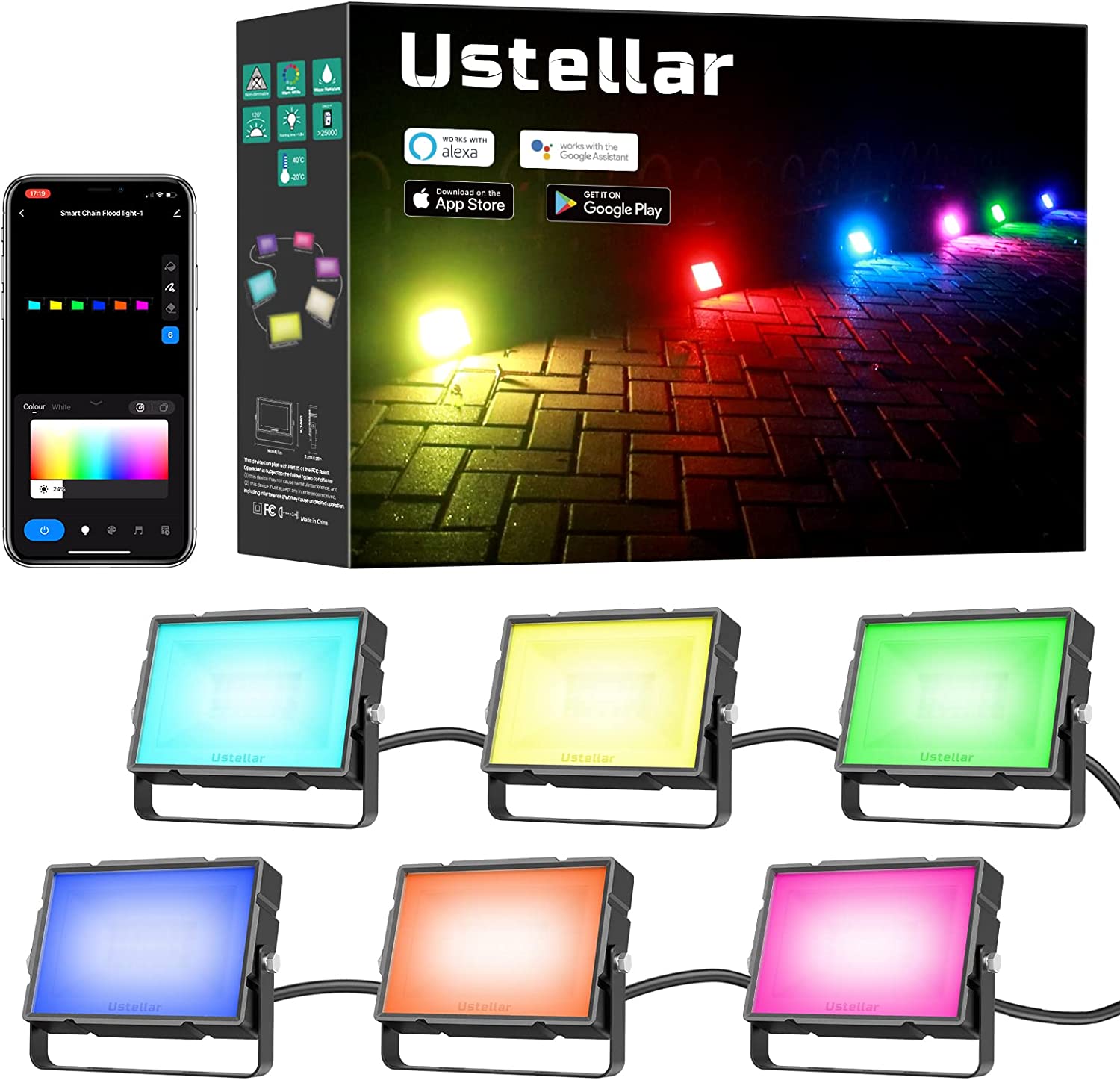
Ustellar RGB Flood Light Outdoor, Smart WiFi RGBW Color Changing Landscape Lights+Warm White 2700K, 40W App Control Christmas Spotlight Works with Alexa, IP66 Waterproof Uplights, Plug & Play (6 Pack)
They have a part number of UT88865-RGBW-US-1.
Fundamentally they are a string of 6 24v WS2814A RGBW flood lights with the first flood as the controller with a Tuya CBU module for wifi control.
At the time of this writing (2023-01-26), the head unit is not flashable via the normal vulnerabilities that tuya-convert uses (as I expected). I’m just not interested in using the Tuya app or their cloud services, so let’s take it apart!
Teardown
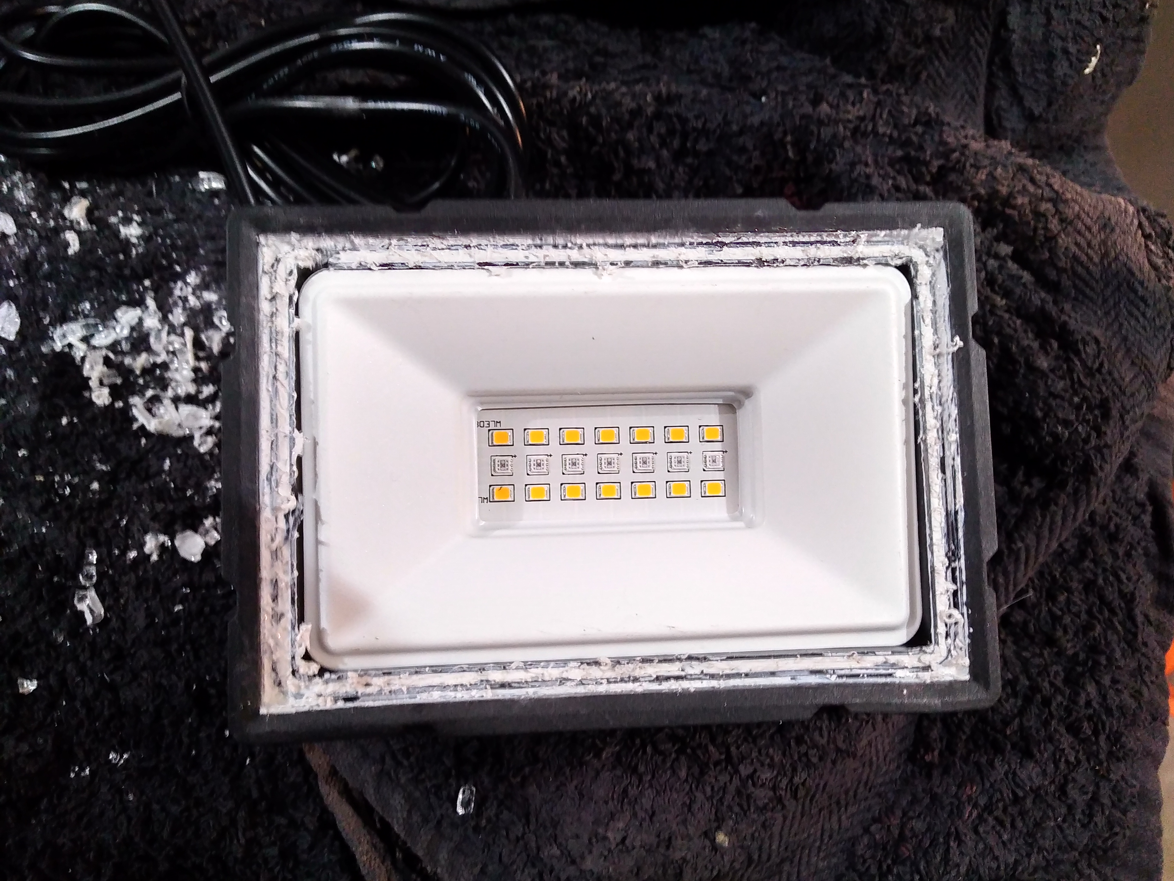
The floodlamp is rated IP66. The gasket for the glass is not something that can be loosened with a heat gun (I tried).
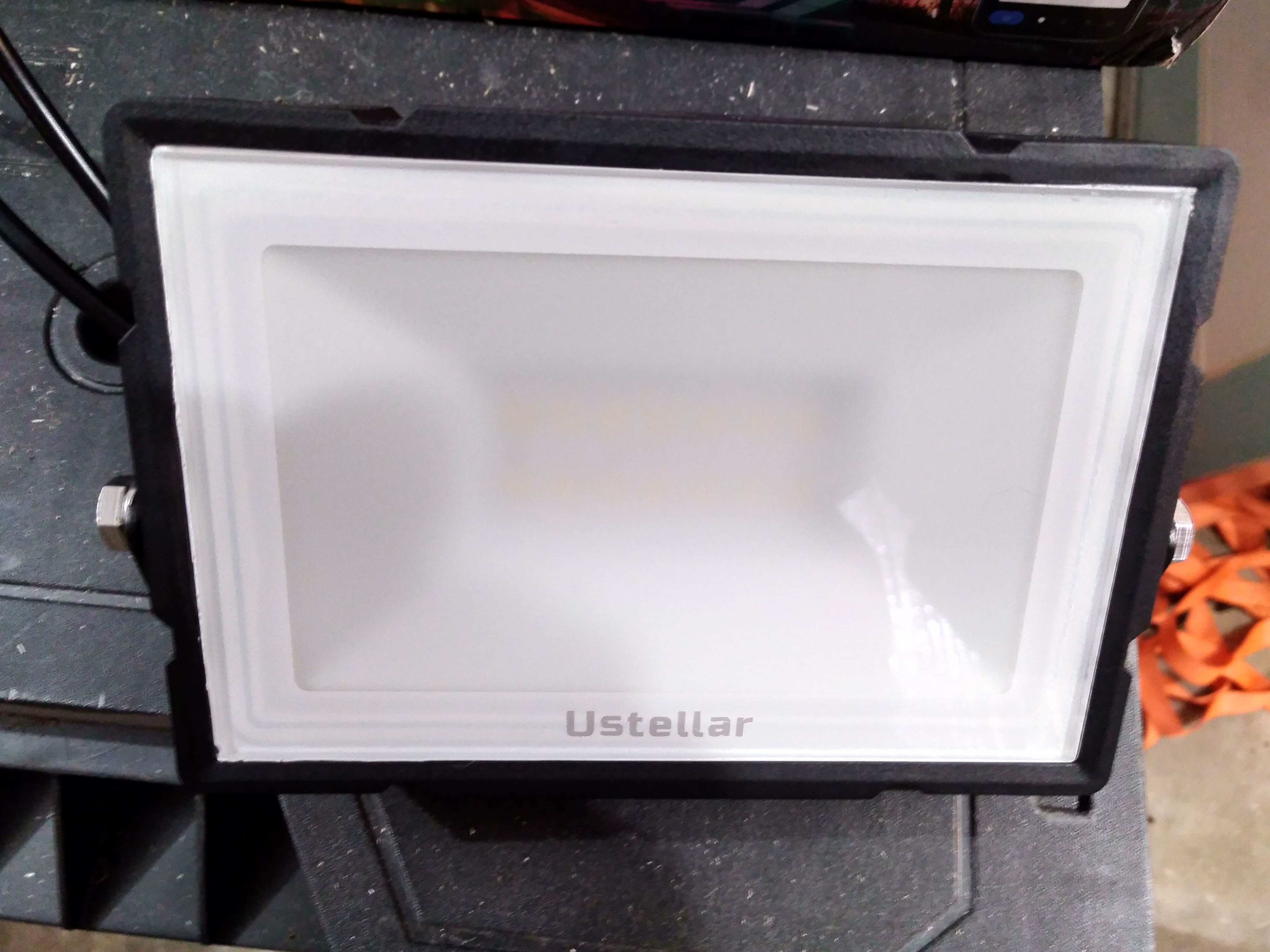
I broke the glass in order to see how it is made:
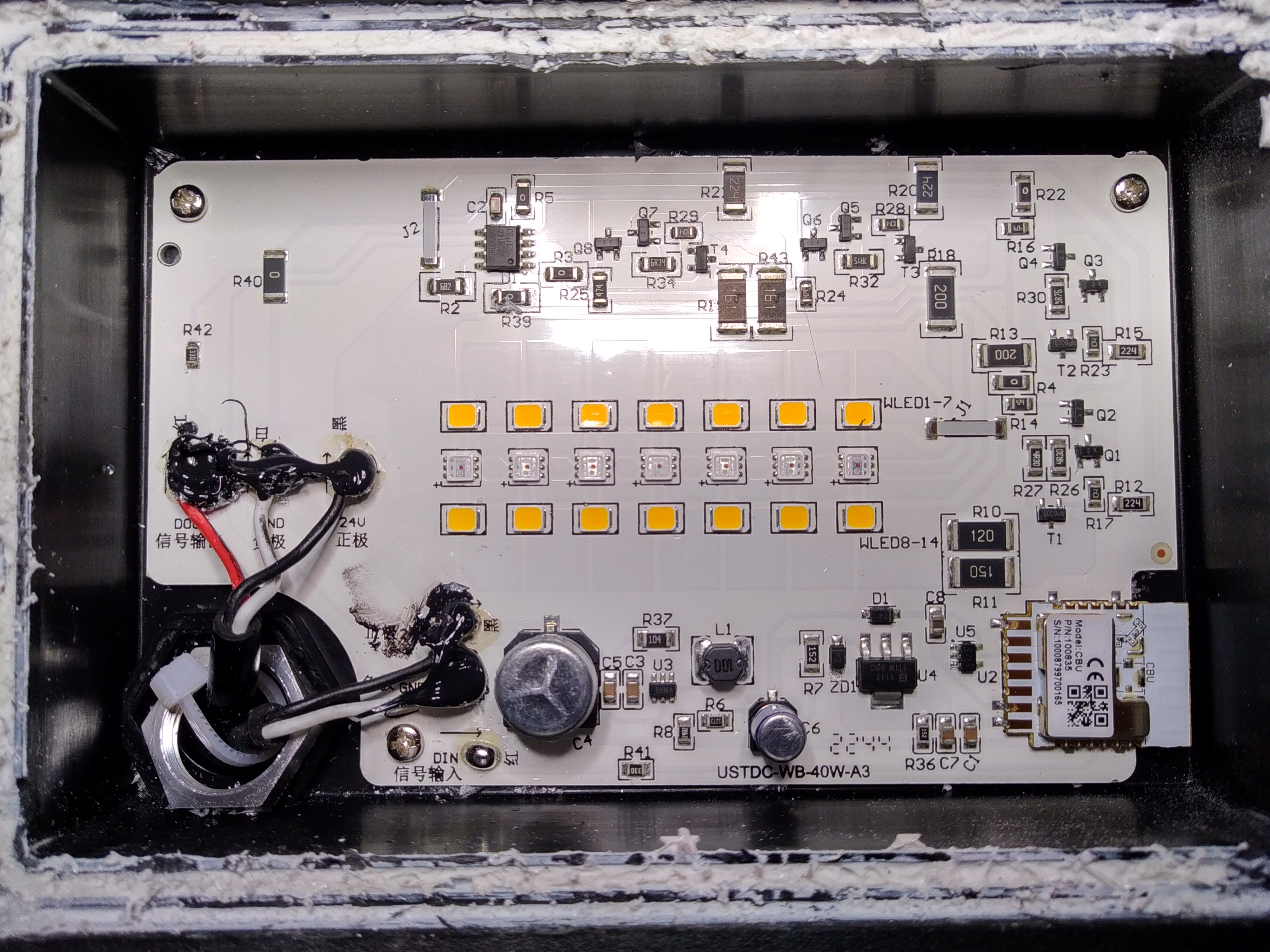
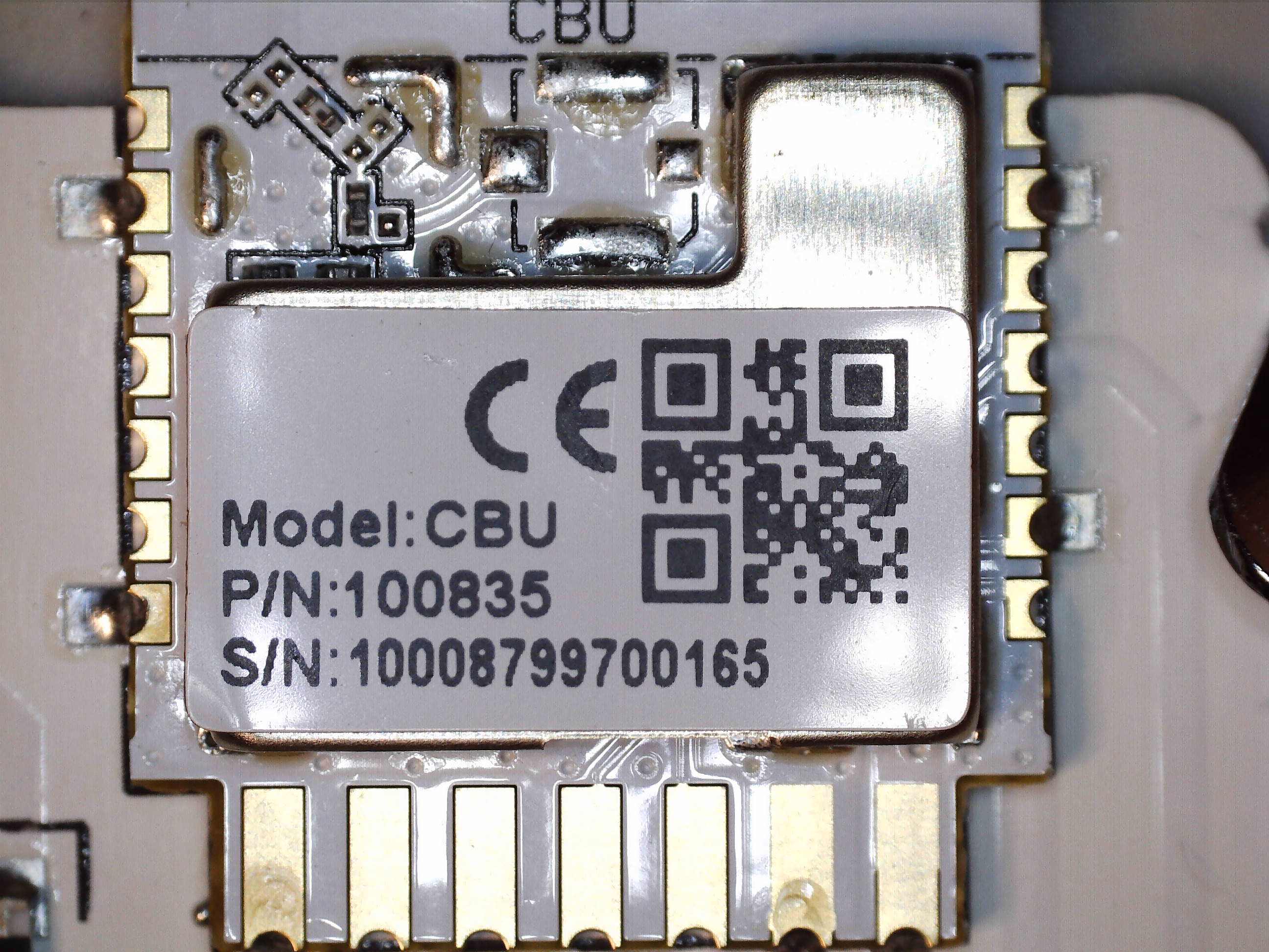
Tuya CBU
You can see the Tuya CBU chip with the embedded wifi antenna in the corner.
This SOC has a BK7231N microcontroller.
There are some tutorials out there for flashing custom firmware on this chip.
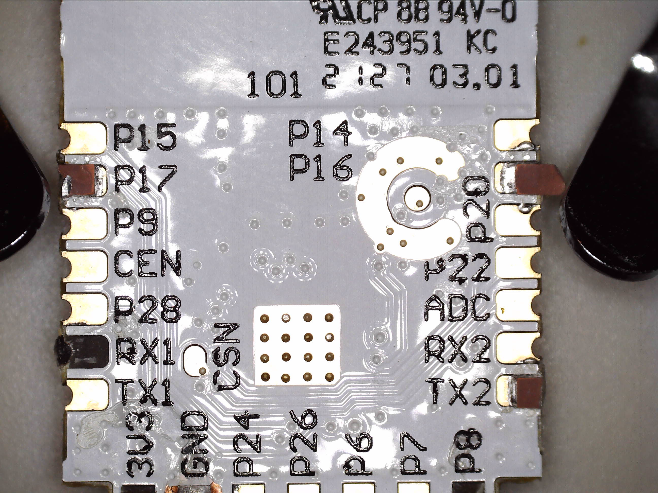
As an aside, I find the markings for: “CP 8B 94V-0 E243951” very curious.
That exact string appears on other parts, specifically the seemingly unrelated “SHARP PN-R556” display.
How in the world are these parts connected?
Some sort of lazy silkscreen copy/paste???
Anyway, the output of this microcontroller’s pin 16 (P16) feeds into the next chip for controlling the LEDs in this flood.
Worldsemi WS2814A
The Worldsemi WS2814A is the next significant part. It takes an input from the Tuya CBU microcontroller and outputs Red, Blue, Green, and White signals for the LED drivers.
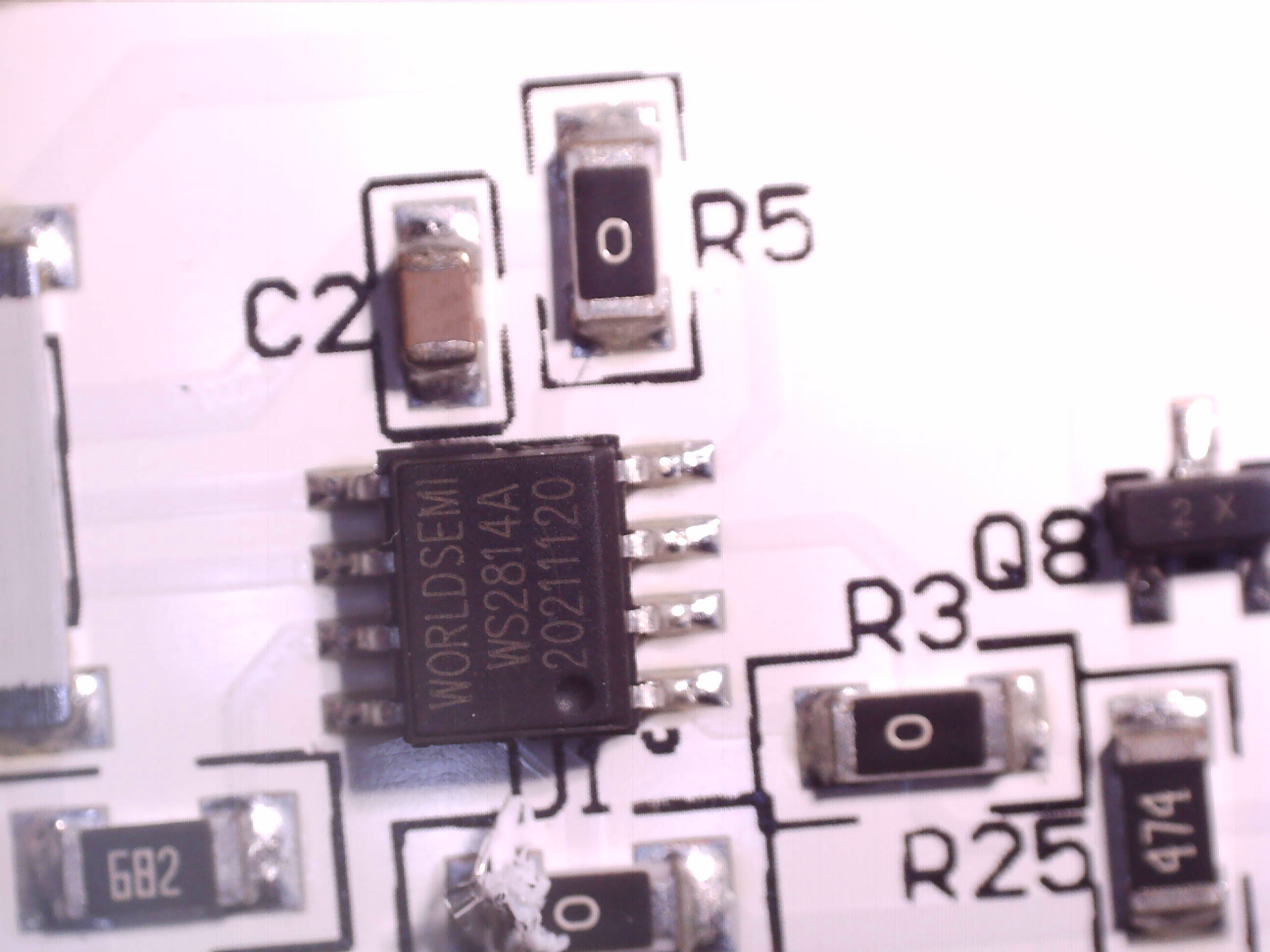
The motherboard is wired to take the input from the microcontroller if present (as it is on the first Flood Light in the package) OR from the DIN line to the motherboard, which is wired up in the subsequent floods.
Wiring
The wiring between lights looks like this:
Note: The power supply’s wires may not be color coded like this. Always double check the polarity with a multimeter.
Conclusion
Honestly, I’m not that interested in repurposing or flashing the Tuya CBU. I would rather these as “dumb” inexpensive WS2814 lights with my own controller. Stay tuned for the next blog post the electrical and software configuration required to control these lights directly.
Comment via email